No products
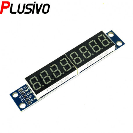
MAX7219 8-Digit LED Display
0104110000011527
New product
MAX7219 is a LED controller used mainly for 7-segment displays 8 digits. It works in such a way that the serial signal is sent through the 4-pin SPI.
See Description for more details about the product.
Add to cart now!
21 Items
- Write a review
More info
Overview
MAX7219 is a LED controller used mainly for 7-segment displays 8 digits. To use the serial signal is sent through the 4-pin SPI.
MAX7219 is an integrated serial input/output common-cathode display driver, which connects a microprocessor and an 8-digit 7-segment digital LED display, and can also connect to a bar graph display or 64 independent LEDs. It includes an on-chip B-type BCD encoder, multi-channel scanning loop, segment word drive, and an 8*8 static RAM to store each data. Only one external register is used to set the segment current of each LED.
A convenient four-wire serial interface can be connected to all general-purpose microprocessors. Each data can be addressed without rewriting all the displays when updating. MAX7219 also allows users to select encoding or not encoding for each data. The entire device includes a 150μA low-power shutdown mode, analog and digital brightness control, a scan limit register allowing users to display 1-8 bits of data, and a detection mode that makes all LEDs glow.
Only 3 IO ports can drive 8-bit glow tube! No flicker when the glow tube is displayed! Support cascading! The display effect is shown in the figure below:
The glow tube and the PCB board are connected by 2.54mm pitch round hole pin headers, which can easily replace the glow tube! Here is another back view:
The four corners of the PCB board are fixed by copper studs, which can effectively prevent accidents such as short circuits from happening!
The glow tube is a 0.36 inch 4-in-one common cathode glow tube
This module is compatible with 5V/3.3V single chip (51/AVR/STM32...)
Wiring instructions (take the provided program as an example, you can connect any IO port, just modify the port definition in the program):
VCC→5V
GND→GND
DIN →P00
CS →P01
CLK→P02
Specifications
- VCC: 5 V
- GND: Ground
- DIN: P00
- CS: P01
- CLK: P02
- Point Distance: 2.54 mm
- Compatible with 3.3 V or 5 V Microprocessor
Precautions
1. Do not connect VCC and GND reversely, so as not to burn the chip
2. 51 Single chip P0 port needs to be connected with a pull-up resistor, if your single chip does not have a pull-up resistor, you can connect the data line to other ports
Don't delay, buy today.
Add to cart now!
Reviews
Customers who bought this product also bought:
-
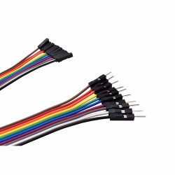
10 cm 40p...
Ideal wires for making connections between...
₱49.00
-
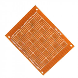
Prototyping...
This is a 70 x 90 mm universal PCB, suitable to...
₱39.00
-
RFID Card...
RFID Card 13.56 MHz
₱13.00
-
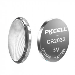
CR2032 battery
CR2032 3V Lithium Manganese Battery for...
₱10.00
-
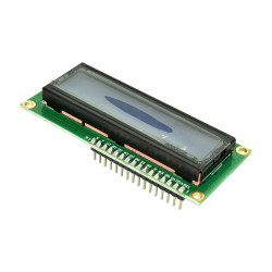
5V LCD with...
This 16 x 2 LCD with blue backlight was...
₱119.00
-
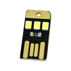
Mini USB Lamp
This product is a portable device that is ultra...
₱19.00
-
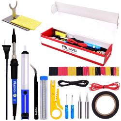
Plusivo...
Complete Soldering Kit: It includes the...
₱279.00
-
10 cm 40p...
Ideal wires for making connections between...
₱49.00
-
L293D Motor...
This motor driver shield is based on L293D...
₱99.00
-

20W Glue Gun...
Hot melt glue gun, multicolor manual glue gun,...
₱78.00


